7 Tips for Choosing a USB C Bulkhead Connector
Choosing a Usb C Bulkhead Connector is not just a matter of matching a port to a panel hole. The right choice affects sealing, cable strain, signal performance, and service life. Small details matter. A connector may look robust on a bench yet loosen after repeated cable pulls or exposure to vibration.
Market context helps explain why dependable USB-C interfaces matter. IDC reported that global smartphone shipments grew 6.4% in 2024, reaching 1.24 billion units, in its January 2025 Worldwide Quarterly Mobile Phone Tracker. That figure describes smartphone shipments, not bulkhead connector demand. Still, it reflects the scale of devices using USB-C connections. The USB Implementers Forum’s USB Type-C specifications define interface requirements, but a connector’s shape alone does not guarantee a particular charging rate, data speed, or durability rating. That distinction is easy to miss.
This guide presents seven practical checks for comparing connectors: panel thickness, mounting style, ingress protection, contact materials, current rating, data capability, and cable compatibility. Look closely at the product datasheet. Confirm the tested sealing conditions, not just an IP label, and check whether the stated speed applies to the complete connection. A small mismatch can mean slow transfers or a poor fit. Some specifications remain unclear, even among reputable listings; verify them with the manufacturer before designing around them. These checks help engineers and buyers select a connector suited to the actual enclosure, environment, and use pattern.
What a USB-C Bulkhead Connector Is and How It Works
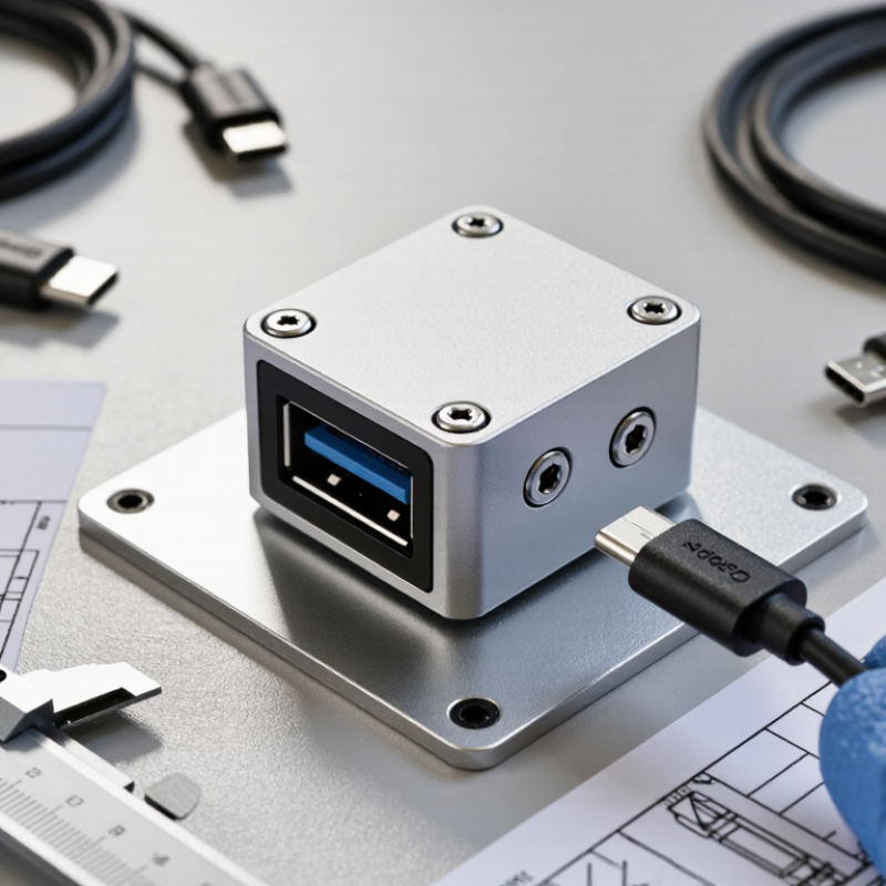
A USB-C bulkhead connector creates a pass-through point in a panel, enclosure, or equipment housing. Its outer socket accepts a standard USB-C plug, while the rear connects to a cable, circuit board, or internal socket. The exact arrangement varies. Some assemblies use a short attached lead; others expose solder or board-level contacts. Check the product drawing before planning the cutout.
USB-C plugs are reversible, so they can be inserted either way. Inside the connector, separate contacts carry power and data, while the metal shell can help provide shielding when properly bonded. A bulkhead fitting does not automatically support every USB-C feature. Charging level, data rate, and video capability depend on its wiring, components, and connected devices. Details matter.
For installation, measure the panel thickness and mounting hole, then confirm the connector’s fastening method. A gasket may reduce dust or moisture entry, but it does not prove a specific sealing performance. That assumption is easy to make. Also consider cable strain behind the panel: a tight bend can stress the connection over time. A connector may look simple from the outside, yet its internal termination can limit the whole link. Check the stated ratings and inspect the rear connection before relying on it.
How to Define Your Application and Connection Requirements
Tip: Map the installation before comparing connector drawings. Record panel thickness, cutout diameter, rear clearance, cable bend radius, and exposure to spray, dust, or vibration. A connector may fit the opening but clash with a bracket once the cable is attached. Sketch the enclosure and measure it. Small details matter.
Define what the connection must carry: charging power, data, video, or basic device access. The USB Implementers Forum’s USB Power Delivery 3.1 specification supports power delivery up to 240 W with Extended Power Range. That figure depends on a compatible system, not the connector alone. Specify the device, cable, host, and operating load together. Not every USB-C port provides the same functions.
Tip: Make requirements testable. List target voltage and current, data protocol, mating cycles, sealing level, and operating temperature. Ask for drawings and test conditions, not just a headline rating. Check whether an ingress-protection rating applies while the connector is mated. This is often missed. Leave room for cable movement; a tidy bench setup may not reflect the installed conditions.
Which Electrical and Data Specifications to Compare
Tip: Compare the rated voltage and current with your equipment’s actual needs. Check the connector’s contact ratings and any temperature derating, especially inside a sealed enclosure. A USB-C shape alone does not confirm USB Power Delivery support. The source, cable, and bulkhead connector must all support the intended power profile.
For data, verify the supported USB mode and speed in the product specifications. USB-C may carry USB 2.0 data, faster USB signaling, or other supported protocols; the shell shape does not tell you which. Check pin assignments, signal integrity details, and shielding. A fast cable cannot compensate for a connector assembly rated for a slower link. Test the complete setup at the expected cable length.
Tip: Check continuity and fit before installation. Confirm that the connector’s mounting hardware suits the panel thickness, then inspect the datasheet for operating temperature and ingress protection. These details are easy to overlook. A neat specification table can still leave questions about real-world performance, so ask for test conditions when ratings seem unclear. If possible, test a sample with your host device and cable before ordering in bulk.
USB-C Data-Rate Capability Benchmarks
Compare the data-rate capability required for your application when evaluating a USB-C bulkhead connector. These are maximum theoretical interface rates, not guaranteed transfer speeds. A USB-C connector’s shape alone does not define its data capability; the connector assembly, cable, host, and device must all support the selected mode.
How to Assess Mounting, Materials, and Environmental Protection
A USB-C bulkhead connector is only as dependable as its mounting interface. Check the panel thickness, cutout dimensions, fastener clearance, and cable bend radius before ordering. A connector that fits the hole may still twist when a stiff cable is pulled. Use a gasket compressed evenly against a flat, clean surface; paint ridges and burrs can create leak paths. Small details matter. IEC 60529 defines IP protection tests: an IP67 rating includes dust protection and temporary immersion up to one metre for 30 minutes under specified conditions. That rating does not guarantee the same protection after poor installation, repeated vibration, or seal damage. Test the installed assembly, not just the connector.
Material choice depends on exposure and service conditions. Stainless steel resists corrosion well, while anodized aluminum can reduce weight; either can disappoint if coatings, threads, or mating surfaces are damaged. For outdoor equipment, inspect the gasket material’s temperature range and compatibility with oils or cleaning agents. USB-IF’s USB Power Delivery 3.1 specification supports power profiles up to 240 W, but the bulkhead connector, cable, and termination must all carry the required rating. More power means more attention to contact resistance and heat. A neat-looking seal is not proof. Recheck torque and sealing after installation; this step is easy to overlook.