Insulated Terminals look small, yet each crimp can affect a system’s reliability. For global buyers, choosing among ring, spade, blade, butt-splice, and other designs means checking more than price. Wire size, insulation material, barrel shape, operating temperature, and tool compatibility all matter. A terminal that fits the drawing may still fail in the field if its crimp is loose or its insulation cannot withstand heat, vibration, or moisture.
Demand for dependable electrical connections is growing alongside electrification. The International Energy Agency’s Global EV Outlook 2024 projected nearly 17 million electric-car sales worldwide that year, representing more than one in five new cars sold. This is not a terminal-market forecast, but it illustrates the expanding range of electrical assemblies that require sound connections. Specifications and testing deserve close attention. IEC 61210 and UL 486A-486B provide relevant reference points for terminal and connector requirements; buyers should confirm which standards apply to their products and markets.
W. Edwards Deming’s quality principle—“Quality comes not from inspection, but from improvement of the production process”—offers a useful lens for terminal selection. A good part cannot rescue an inconsistent crimping process. Small details count. This guide compares ten common Insulated Terminals by application, connection style, and practical selection factors. It also acknowledges a limitation: product names and ratings vary by manufacturer, so buyers should verify current datasheets before ordering. The right choice is rarely just the cheapest one. It is the one that fits the conductor, tooling, environment, and documented requirements.
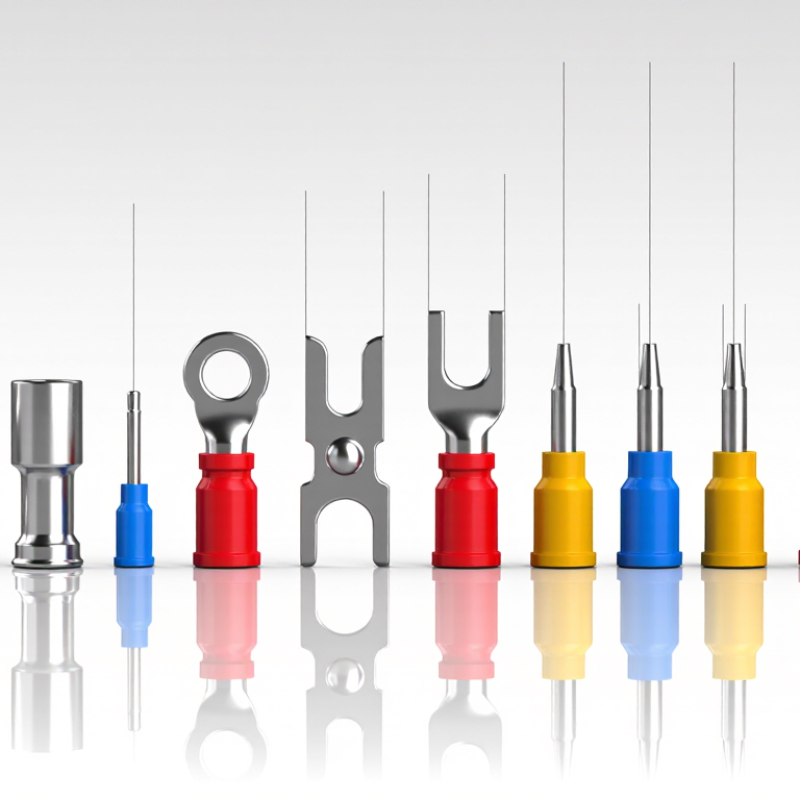
Before comparing terminal types, confirm the conductor size and insulation diameter each one is designed to accept. IEC 60352-2 provides requirements, test methods, and practical guidance for crimped connections. It does not make every terminal interchangeable. Check the applicable standard edition and the terminal’s specified wire range.
Fit is not obvious. A conductor should sit fully inside the barrel, with insulation clear of the electrical crimp area. Strip length matters: too little exposed copper can weaken contact; too much may leave strands outside the barrel. Use the specified tooling and crimp settings. Record relevant dimensions, such as crimp height, where the terminal specification calls for them.
A neat-looking crimp is not proof. Inspect sample connections for stray strands, damaged insulation, or a barrel that is visibly underfilled. Then validate the wire-terminal combination using the applicable mechanical and electrical tests. Requirements and acceptance limits depend on the product specification, so avoid assuming one measurement fits all. Still, the first sample can mislead; repeat checks across the intended wire range and production setup. A small mismatch can become a loose connection in service.

Fastener access can determine whether a terminal is practical in a crowded panel. Ring terminals need the nut or screw removed, then provide a closed connection that resists slipping off. They suit fixed joints, but changing one takes more time. Fork terminals slide beneath a loosened fastener, so maintenance is quicker. The trade-off is less retention if the screw backs out. Access matters.
Hook terminals can catch around a screw head with limited loosening. Check the hook’s orientation and seating; a poorly positioned connection may work loose. Flag terminals turn the wire connection sideways, helping where a straight approach is blocked by a panel wall or neighboring wire. They do not remove the need to reach the fastener itself. Small details matter.
Tips: Before choosing, mock up the connection with the actual screw, tool, and wire route. Leave room for the driver to turn. Confirm the terminal fits the conductor and fastener size, and follow the equipment maker’s installation guidance. A cramped fit can look fine on a drawing. In practice, it may not.
Blade, bullet, and pin terminals may all have insulated sleeves, but their mating styles differ. A blade terminal uses a flat metal tab that slides into a matching receptacle. Its broad contact faces make alignment easy to see. Check tab width and thickness; a close-looking match can still feel loose.
A bullet terminal connects through a rounded male end and a matching tubular socket. The parts push together along one axis, often with a distinct snug feel. That matters in compact wiring harnesses where connections may be disconnected for service. Do not judge fit by insulation color alone. The metal dimensions and grip are what count.
A pin terminal has a narrow, straight conductor that enters a compatible socket or connector opening. It suits connections where a small contact must fit into a defined space. Fit is tactile. Still, tactile checks are not enough: confirm the terminal’s dimensions, wire range, and intended connector match. A practical inspection looks for exposed strands, damaged insulation, and a connection that slips apart with little effort. Small differences can be easy to miss on a drawing, so verify samples before ordering in volume.
A classification of ten common terminal types by their primary connection style. Counts show how many types in this overview use each style; they are not market-share or sales figures.
How to distinguish them: Blade terminals slide onto a flat tab; bullet terminals connect a rounded male pin to a matching female socket; pin terminals insert into a compatible receptacle. Ring and fork terminals fasten to a stud or screw, while butt splices join wires and ferrules prepare stranded wire ends for clamping.
Grouping terminals by joining method makes selection clearer than comparing shapes alone. Butt splices join two wire ends in one sleeve, creating an end-to-end connection. Parallel splices bring conductors together side by side, useful when a branch connection is needed. Ferrules are different: they bundle fine strands at a wire’s end for insertion into a clamp terminal. They do not join two wires.
Small distinction. It matters.
The right choice depends on conductor size, strand class, insulation, and the receiving terminal. A splice barrel must match the wire; the crimp tool and die must match the connector. A loose crimp can raise resistance, while excessive compression may damage strands. A tidy appearance is not proof of a sound joint.
NFPA’s Home Electrical Fires report estimates 46,700 U.S. home fires annually involved electrical failure or malfunction during 2015–2019. This figure covers many electrical causes, not terminals alone, but it highlights why workmanship deserves attention. Some field choices still rely too heavily on habit.
Tips: Strip only the specified length. Check that no strands are cut or exposed beyond the barrel. For ferrules, confirm the pin fits the terminal opening before tightening. Keep a sample crimp for inspection; visual checks can miss weak compression.
For insulated ring, fork, and quick-disconnect terminals, confirm conductor size before choosing a barrel. A 10 AWG conductor has a nominal cross-sectional area of approximately 5.26 mm², as listed in ASTM B258, the standard for AWG wire dimensions. That conversion is useful, but it does not make every 10 AWG terminal interchangeable. Check the terminal’s stated wire range, conductor material, and strand construction. A loose fit can pull free; an overfilled barrel may crimp poorly. Small details matter.
Metric labels can cause confusion. IEC 60228 lists 6 mm² as a standard nominal conductor size, while 10 AWG is about 5.26 mm². These values are close, not identical. Do not assume a terminal marked 6 mm² will always suit 10 AWG. Check the manufacturer’s crimp range and, where possible, make a sample crimp and inspect it for full compression and exposed strands. I still double-check the marking against the wire specification; conversions are easy to misread. Also measure the conductor, not its insulation, which can make the cable look much larger.
| Terminal Type | Connection Style | Common Conductor Range | Typical Mating or Fit Detail | Common Applications |
|---|---|---|---|---|
| Ring Terminal | Closed ring secured by a screw or stud | Commonly available for 22–16, 16–14, and 12–10 AWG | Choose the ring opening to match the fastener, such as M4, M5, or M6; confirm dimensions before ordering. | Grounding points, control panels, battery connections, and equipment wiring |
| Fork (Spade) Terminal | Open-ended fork secured beneath a screw head or nut | Commonly available for 22–16, 16–14, and 12–10 AWG | Fork width and opening must suit the terminal screw or stud; the open design can simplify removal. | Control cabinets, appliances, and connections requiring occasional service |
| Hook Terminal | Curved open hook placed around a screw | Commonly available for small control-wire sizes, including 22–16 and 16–14 AWG | Check hook opening and screw size; intended for compatible screw-terminal connections. | Low-voltage controls, instrumentation, and compact electrical assemblies |
| Pin Terminal | Insulated crimp barrel with a narrow projecting pin | Commonly available across several ranges, including 22–16, 16–14, and 12–10 AWG | Pin diameter and length must fit the terminal block; ferrule-style pins are a separate connector design. | Terminal blocks and screw-clamp connections that accept a pin end |
| Female Quick-Disconnect Terminal | Receptacle slides over a compatible flat tab | Commonly available for 22–16, 16–14, and 12–10 AWG | Match receptacle width and tab thickness; common tab widths include 2.8, 4.8, and 6.3 mm. | Appliances, automotive wiring, and serviceable equipment connections |
| Male Quick-Disconnect Terminal | Flat tab mates with a compatible female receptacle | Commonly available for 22–16, 16–14, and 12–10 AWG | Match tab width and thickness to the female receptacle; common tab widths include 2.8, 4.8, and 6.3 mm. | Appliance harnesses, control equipment, and plug-in wiring connections |
| Male Bullet Terminal | Round pin mates with a compatible female bullet connector | Commonly available for 22–16, 16–14, and 12–10 AWG | Match bullet diameter and connector series; male and female parts must be designed to mate. | Vehicle harnesses, lighting circuits, and removable wiring assemblies |
| Female Bullet Terminal | Round socket accepts a compatible male bullet connector | Commonly available for 22–16, 16–14, and 12–10 AWG | Confirm socket diameter and fit with the matching male bullet terminal. | Vehicle wiring, lighting, and compact detachable connections |
| Insulated Butt Splice | Two wires are inserted from opposite ends and crimped | Commonly available for 22–16, 16–14, and 12–10 AWG | Select a splice rated for both conductor sizes; use the specified crimping tool and method. | In-line wire repairs, harness extensions, and wire-to-wire joins |
| Insulated Parallel Splice | Two conductors are joined side by side within a crimp barrel | Available in multiple conductor combinations; confirm the listed wire-size range for the specific part. | Check that the barrel accepts the intended combination and total conductor size. | Branch connections and wiring assemblies where a parallel crimp joint is suitable |
Size reference: 10 AWG has a nominal conductor cross-sectional area of approximately 5.26 mm². Terminal size ranges and mating dimensions vary by product and applicable standard; verify the product specification, conductor construction, and crimping requirements before selection.
Please share your email with us to see your results.