Choosing the right Pipe Swaging Machine can determine your production speed, joint quality, and long-term operating costs. The decision should match your materials, tube dimensions, daily workload, and required finish. A compact workshop machine may handle occasional copper tubing, while heavy steel pipes demand greater force, rigid tooling, and stable hydraulic control.
Look closely at machine capacity. Check the maximum pipe diameter, wall thickness range, motor power, stroke length, and forming accuracy. Ask whether the tooling supports your common pipe profiles. A machine that appears powerful may still perform poorly with thick walls or difficult alloys. That detail matters.
Reliability depends on more than specifications. Experienced buyers inspect frame construction, die alignment, safety controls, maintenance access, and spare-parts availability. Request sample results using your actual pipe material. Examine the swaged end under proper lighting. Uneven reduction, surface marks, or small cracks can reveal problems that brochures never mention.
Supplier support also deserves careful attention. Look for documented testing, clear operating instructions, responsive technical service, and transparent warranty terms. Industry certifications can help, but they should not replace practical verification. No checklist is perfect. Production conditions change, and operators may expose weaknesses during real work.
A sensible selection process compares total ownership costs, not only the purchase price. Include energy use, tooling replacement, setup time, training, and likely downtime. The best Pipe Swaging Machine is not always the largest or fastest model. It is the one that delivers consistent results safely, fits your workflow, and remains supportable for years. unerquicklich
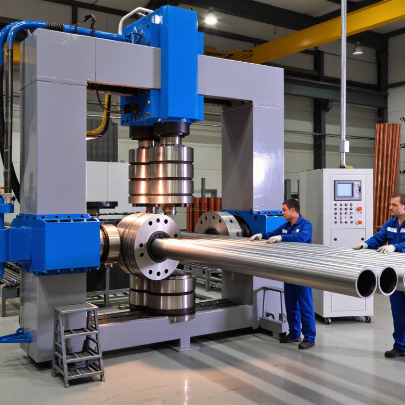
A pipe swaging machine reshapes a tube end through controlled radial force. It can reduce, expand, taper, or form a joint-ready profile without cutting away material. Picture a stainless-steel tube entering the tooling, then leaving with a clean, concentric shoulder. This process supports HVAC lines, vehicle exhaust systems, hydraulic assemblies, heat exchangers, and structural tubing. The right machine depends on tube diameter, wall thickness, material hardness, and required production volume.
Industry data gives useful context. The U.S. Department of Energy reports that compressed-air systems can waste 20–30% of their output through leaks and poor maintenance. Pneumatic swaging equipment therefore needs efficient air controls, accessible seals, and measurable operating pressure. Electrical models may suit stable factory lines, while hydraulic systems often handle thicker or harder alloys. Do not select by maximum force alone. Tooling range, stroke length, repeatability, changeover time, and operator visibility affect real productivity.
In practical trials, inspect the first formed tube under magnification. Look for wrinkles, surface marks, uneven wall flow, and springback. A machine may meet its brochure capacity yet fail your actual alloy. That assumption can be wrong. The American Society of Mechanical Engineers emphasizes process control and inspection across pressure-containing components. Record forming force, dimensions, and cycle time before purchase. A small pilot test often reveals more than a polished specification sheet.

Choosing a pipe swaging machine starts with the material, not the advertised tonnage. Carbon steel needs high forming force and controlled lubrication. Stainless steel resists deformation and can work-harden during repeated passes. Aluminium forms more easily, but it can mark under excessive die pressure. The World Steel Association reported 1,888.2 million tonnes of crude steel production in 2023. The International Aluminium Institute reported about 70.6 million tonnes of primary aluminium production. These volumes reflect different processing realities, not identical machine requirements.
Measure outside diameter, wall thickness, length, and tolerance before selecting equipment. A thin-wall tube may buckle during reduction. A thick-wall pipe may require several passes, annealing, or a larger drive system. Rotary swaging suits gradual diameter reduction and repeatable concentricity. Press swaging works well for shorter parts and stronger local forming. Expansion, tapering, and end-necking require different tooling clearances. ASME B16.9 and relevant ASTM material standards can guide dimensional and material checks, but they cannot replace a production trial.
Tips: Test the actual alloy and wall thickness. Record force, speed, die wear, and springback. Inspect the first ten parts. Then review the settings. A clean surface is not enough. Check hardness and ovality too. In my experience, machine capacity is often overestimated because catalog ratings ignore tooling condition and pass sequence. That assumption deserves challenge. A trial piece may expose cracking, wrinkles, or hidden dimensional drift before expensive dies are commissioned.
Use the table below as a practical starting point for matching pipe material, size, wall thickness, reduction requirement, and production needs with an appropriate swaging machine configuration.
| Pipe Material | Typical Material Condition | Common Outside Diameter Range | Typical Wall Thickness | Suitable Swaging Process | Recommended Machine Configuration | Tooling Considerations | Main Selection Priority |
|---|---|---|---|---|---|---|---|
| Low-carbon steel | Annealed, normalized, or cold-drawn tube | 10–100 mm | 0.8–6 mm | Rotary swaging Tube end reduction Taper forming | Hydraulic or mechanical machine with adjustable die stroke and firm workholding | Hardened tool steel dies; use lubrication to reduce friction and die wear | Required forming force and repeatability |
| Stainless steel | 304/316-type austenitic stainless tube; annealed or cold-worked | 6–80 mm | 0.5–4 mm | Rotary swaging Necking Multi-pass reduction | High-rigidity machine with controlled speed, accurate alignment, and cooling capability | Polished, wear-resistant dies; allow extra passes for work-hardening materials | Work hardening, surface finish, and die life |
| Aluminum alloys | Annealed or solution-treated tube; common wrought alloys | 8–120 mm | 0.6–5 mm | Rotary swaging End tapering Light reduction | Servo-controlled or mechanical machine with moderate forming force and precise stroke control | Highly polished dies with generous radii to minimize galling and surface marking | Surface protection and dimensional accuracy |
| Copper and copper alloys | Annealed, half-hard, or cold-drawn tube | 6–100 mm | 0.5–4 mm | Rotary swaging Tube end forming Groove preparation | Variable-speed machine with accurate die closure and controlled feed | Polished dies; select die material and lubricant to prevent pickup | Ovality control and prevention of surface damage |
| Titanium alloys | Annealed aerospace or medical-grade tube | 6–60 mm | 0.5–3 mm | Low-speed rotary swaging Small-step reduction | Rigid, precision machine with low-clearance tooling, controlled speed, and reliable lubrication | Premium wear-resistant dies; avoid excessive reduction per pass | Heat generation, cracking risk, and dimensional control |
| Nickel-based alloys | Annealed or solution-treated high-temperature alloy tube | 10–75 mm | 1–5 mm | Heavy-duty rotary swaging Multi-pass forming | High-force hydraulic or mechanical machine with rigid frame and process monitoring | High-strength dies with excellent alignment and controlled lubrication | High forming load and resistance to work hardening |
| Carbon-fiber or composite tube | Finished composite tube or metal-lined composite assembly | 15–100 mm | Material-dependent | Low-pressure sizing Crimping Assembly-only forming | Special-purpose press or controlled crimping system; conventional metal swaging may be unsuitable | Non-marking, contoured tooling with carefully limited compression | Preventing fiber damage, delamination, and local crushing |
| Thin-wall tube | Any ductile metal with a high diameter-to-wall-thickness ratio | 20–150 mm | Below 1.5 mm | Light rotary swaging Mandrel-supported forming | Precision machine with adjustable reduction rate, internal support, and accurate tube guidance | Close-fitting mandrels and polished dies to prevent wrinkling or collapse | Wrinkling, buckling, and wall-thickness variation |
| Thick-wall tube | High-strength steel, stainless steel, or nickel alloy tube | 20–150 mm | 4–12 mm | Heavy reduction Multi-pass swaging End sizing | High-capacity hydraulic or mechanical machine with strong clamping and high peak force | Large-radius, high-strength dies; verify die stress and machine capacity | Peak force, rigidity, and heat management |
| Precision finished tube | Cold-drawn tube requiring a tight finished diameter | 10–80 mm | 0.8–5 mm | Sizing Calibration Light reduction | Servo-controlled machine with programmable stroke, feed, and repeatable die positioning | Matched die sets with fine adjustment and documented inspection dimensions | Diameter tolerance, concentricity, and repeatability |
| High-volume production tube | Stable incoming material with consistent dimensions and batch properties | 10–100 mm | 0.8–6 mm | Continuous rotary swaging Automated feeding Repeat forming | Automated machine with programmable controls, automatic feeding, guarding, and quick-change dies | Modular die sets designed for fast changeover and predictable service life | Cycle time, uptime, and process consistency |
| Prototype or low-volume work | Multiple metals, sizes, and changing part geometries | 6–100 mm | Material-dependent | Manual loading Single-pass forming Trial reduction | Flexible machine with quick tooling changes, adjustable settings, and accessible controls | Interchangeable die sets covering the intended diameter range | Versatility, setup time, and tooling cost |
Important: The diameter and wall-thickness ranges are general engineering guidelines, not guaranteed machine capacities. Final selection should be confirmed through forming trials using the actual alloy condition, tube geometry, reduction ratio, tolerance, production rate, and required surface finish. For hollow tubes, check whether internal mandrel support is required to prevent collapse or excessive ovality.
Machine capacity should match your real production range, not your largest imaginable pipe. Check maximum diameter, wall thickness, material strength, and required reduction in each operation. A machine with excessive capacity may consume more energy and increase tooling costs. A smaller machine may struggle, create surface marks, or lose dimensional accuracy. In shop evaluations, sample testing often reveals problems that catalog figures hide. Measure finished diameter at several points. Consistency matters.
Tooling options directly affect changeover time and product quality. Confirm whether the machine accepts interchangeable dies, adjustable mandrels, and guides for different pipe profiles. Dies should support the material without leaving dents or uneven transitions. Quick-change tooling sounds useful, but it may disappoint when alignment is difficult. I once focused too heavily on die variety and overlooked setup time. That mistake reduced the expected productivity.
Tips: Compare complete cycle time, not only strokes per minute. Include loading, unloading, lubrication, inspection, and tool changes. Ask for a trial using your actual pipe material and dimensions. Record noise, vibration, temperature, and finished tolerances during repeated cycles. Production speed means little if operators must frequently correct defects. Select controls that show force, position, and alarms clearly. Reliable maintenance access also protects long-term performance.
Automation should match production reality, not showroom promises. The International Federation of Robotics reported 541,302 industrial robots installed worldwide in 2023. That growth shows automation is expanding, but a fully automatic swaging machine may still be excessive for short, varied batches. Check feeding accuracy, changeover time, sensor feedback, and operator training requirements. A useful machine records pressure, stroke position, and fault history. These details help technicians identify worn dies before poor joints reach inspection.
Safety deserves closer attention. Guards should block access during the swaging cycle, while interlocks and emergency stops must remain easy to reach. ISO 12100 supports risk assessment throughout machine design and operation. Lockout procedures also need clear access around hydraulic and electrical components. Small design details matter. A difficult isolation point invites mistakes. Maintenance access should allow die replacement without awkward lifting or exposed pinch points.
The U.S. Department of Energy reports that compressed-air leaks can waste 20–30% of compressor output. Therefore, inspect pneumatic fittings, hoses, and regulators during routine service. Energy monitoring is useful, though not perfect; inaccurate sensors can create false confidence. I would compare measured energy per pipe, not catalogue estimates. The International Energy Agency notes that electric motor systems consume roughly 46% of global electricity use. Efficient drives, standby controls, and correct hydraulic sizing can reduce unnecessary consumption, but only when operators actually use the settings.
How to Choose the Best Pipe Swaging Machine?
Selecting a pipe swaging machine starts with your actual production needs. Measure tube diameter, wall thickness, material, and daily output. Stainless steel may require more forming force than softer alloys. A machine rated only for light tubing can struggle with repeated heavy work. That affects accuracy and service life. Ask for test results using samples similar to your own pipes. A smooth first cycle proves little. Repeated cycles matter more.
Budget should include tooling, installation, electricity, training, and future repairs. A cheaper machine may need custom dies or frequent adjustments. Those costs can quietly exceed the original saving. Check changeover time between pipe sizes. In a busy workshop, ten extra minutes per batch becomes expensive. Quality means stable dimensions, firm clamping, clean swage profiles, and accessible controls. Inspect the frame, hydraulic system, guards, and emergency stop before purchase. Small details matter.
Long-term support is often overlooked. Confirm spare-part availability, technical response times, maintenance instructions, and operator training. Ask who handles faults after the warranty expires. A reliable supplier should explain limitations instead of promising everything. That builds trust. Keep service records and review performance after several months. I would also leave room for doubt: projected output may not match real production, especially during staff changes. A short trial under normal workshop conditions can reveal noise, heat, setup difficulty, and unexpected material waste.
A balanced purchasing decision should evaluate more than the initial price. This practical procurement model gives the highest weight to long-term quality and reliability, followed by total budget impact and supplier support. Compare machines using measurable factors such as forming consistency, operating capacity, energy use, spare-parts availability, warranty coverage, and service response time.
Please share your email with us to see your results.